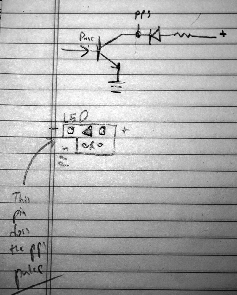
I have this SparkFun GP-20U7 GPS Receiver. It seems to work pretty well. I'm changing around my approach to the autonomous robot, and now I need access to the PPS (Pulse-Per-Second) functionality of the unit. The PPS pad isn't broken out on this device - it's under a pile of red goop you have to scrape off, and is actually part of an unpopulated LED circuit. It's not immediately clear (to me, anyway) how to wire it up to a microcontroller to get the PPS signal.
I've referenced this blog post, which noted that "PPS is open-drain so a pull-up is required. If the LED is installed it is the pull-up."
I think that means the following hastily-drawn diagram applies:

At any rate, I was able to verify that the correct solder pad does some kind of pulse every second (when the device has a fix) with my worlds-cheapest-ebay-kit-oscilloscope. I don't really want to populate the LED/resistors (I don't have the SMD parts), but I believe I can just connect that "left" solder pad to a microcontroller input with an internal pull-up resistor and set an interrupt and be good to go. I'm leaving this blog here for reference since there isn't much about this device online for electronics newbies like me.
(Side note: PPS only pulses when the GPS has a good fix. This makes sense in retrospect, but it's a pain if you have to haul your junk to an open window on the second floor, for example, just to figure out which pad to use. Hypothetically, that is.)